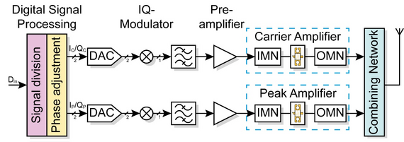
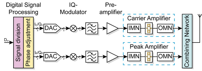
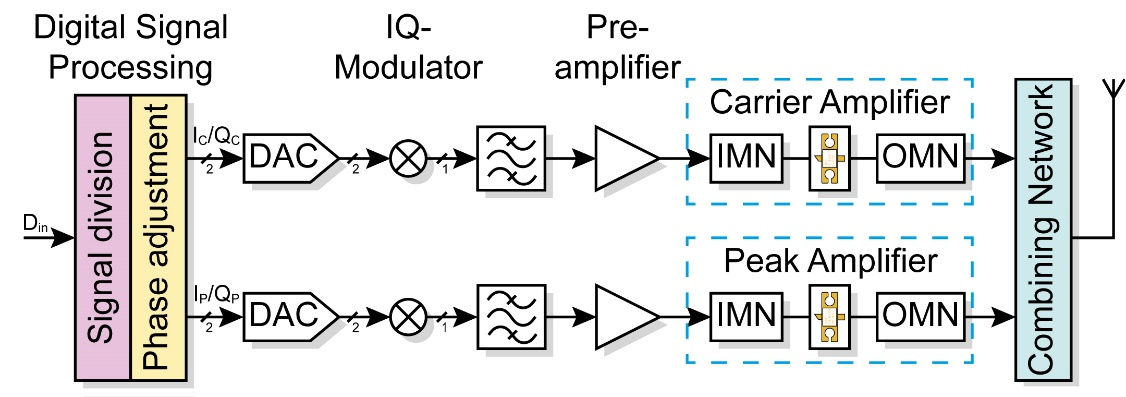
In order to enhance the efficiency of the Doherty amplifier over its full range, the discrete input divider with fixed signal distribution can be removed and each amplifier can be supplied with a signal, that carries the same information but is adjusted in amplitude and phase depending on the input power. The schematic structure of this dual-input Doherty amplifier architecture is shown in Fig. 10.


For this type of signal distribution, two preamplifier sections are required, what makes it possible to double the maximum input power. The signal division is shifted to the digital domain. Every input sample can be modified in amplitude and phase to achieve an overall increase in efficiency. In order to ensure a defined phase difference and a defined amplitude ratio at the inputs of the Doherty-amplifier, regardless of the non-linear gain and phase shift of the preamplifiers, a one-time calibration of both paths is necessary. This calibration also linearizes the preamplifier characteristics. Nevertheless, the input data must be present synchronously on both amplifiers. Therefore a synchronous signal generation must originate from the two transceivers. In addition, the same local oscillator must be used for the modulation, since identical local oscillators oscillate with a similar but not exactly the same frequency, what would result in a constant phase change between the two RF signals.
When splitting the Signal in the digital domain, at the lower power range, the peak amplifier does not contribute to the total output power. To increase efficiency in this range, the entire power is transferred to the main amplifier. When the main amplifier reaches its saturation point, power is also headed to the peak amplifier. In the higher power range, an optimization of the power and phase distribution leads to improved efficiency.


