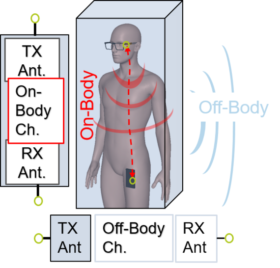
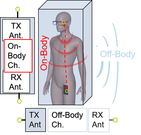
The design of the required antennas for these system is still challenging due to the high level of integration and especially the coupling with the lossy body tissue. For off-body links with the usually used modelling approach according to the Friis transmission equation the body has to be treated as part of the antenna, ref. Fig 1. Furthermore, as can be seen in Fig. 1 on-body links complicate the systematic development even more as antenna and channel cannot be modeled as separate building blocks.


At the Institute of Microwave and Wireless System methods for the systematic development of antennas for devices worn at or implanted in the body are investigated.
Body-centric wireless communication channels


Considering the variety of possible applications of body area networks a rough classification of the communication channels that we are investigating as follows:
-
On-body to on-body path
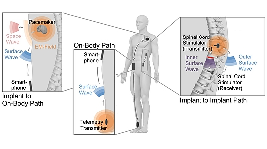
This case is used in the networking of sensors carried on the body. These may be e.g. sensors for the determination of the blood sugar content, oxygen blood count, step counter or heart rate monitor. Already today sensors are connected with a smartphone as an evaluation unit. The propagation scenario is shown by way of example in the lower left part of Fig 2. Since transmitter and receiver are located at the body, propagation takes place through space waves (in case of line of sight) and through body-centric surface waves. Especially the surface guided waves enable interconnection of sensors without a line-of-sight connection.
-
Implant to on-body path
This case, which is illustrated here by the example of the vital parameter’s transmission between a close-surface implanted cardiac pacemaker and an evaluation unit worn at the body, differs from the first case in that one antenna is located in the implant below the body surface. Thus, one antenna is located on the other side of the boundary layer between tissue and air. However, the preferred excited wave type would here be also a surface-guided wave, which propagates along the body contours.
-
Implant to Implant path
Future application could also require a radio link between two implants. As an example, in the upper right part of Fig 2 a sensor and an actuator of a neurostimulator device is shown. Such systems are currently being discussed for bridging severed nerve connections (e.g., cross-section paralysis). In this case, transmitter and receiver would be implanted. Due to the different dielectric tissue parameters the wave propagation still is going to take place partly at the body-air-boundary and partly at the boundary layer between muscle tissue and bones.
Antenna de-embedding – On-body antenna parameters
Due to the coupling of the antennas with the body tissue wave propagation in the on-body domain is more complex than in free-space. Thus, standard antenna characterization methods – like standard free-space radiation pattern – cannot be used to characterize on-body antennas and to quantify the contribution to the transmission coefficient of the studied link. De-embedding of the on-body antennas is the essential issue. Therefore, we developed a method to define adapted on-body antenna parameters linked more closely to the propagation mechanisms [1]. To consider the presence of the human body our method utilizes the Norton surface wave theory to model electromagnetic fields of antennas located at the body. The adaption of the solutions of the Norton surface wave theory, especially the solution of Bannister [2] for the problem of antennas near the human body surface was earlier published [3]. In [8] we derived an on-body far-field definition. Based thereon, on-body antenna parameters (e.g. gain, pattern) are defined following the known basic principles in free-space [8]. These on-body parameters allow direct comparability of different antennas and can be used to calculate the transmission parameters of the on-body links.
Spherical wave functions
Antenna de-embedding


Another option for on-body antenna de-embedding based on the idea to decompose the surrounding on-body field of an antenna [7]. A set of basic functions suitable for this case are the spherical wave functions, hereafter abbreviated as SWFs [6]. An example of this decomposition is shown in Figure 3 for the first six basic functions or so-called SWF modes. The field of the antenna (here integrated into a glasses frame) is recorded on the grey colored box and then decomposed into SWFs. The specific SWF weighting coefficients describe this field completely. Based on the structure in Figure 3, Figure 4 shows an example of these decomposition coefficients.
In a next step we derived a method to directly calculate the aforementioned on-body antenna parameters using the decomposition coefficients. This allows are more intuitively interpretation of the observed complex coefficients usable for the antenna design. The computed on-body antenna gain of the studied example is visualized in Figure 5.


Channel modeling and calculation of the transmission coefficient
One major advantage using SWFs is the separate description of on-body antenna and channel. Besides the decomposition of the antennas, the channel can also be modeled via SWFs using a so-called channel matrix [7 Naganawa Quelle]. The basic process is presented at the center of Figure 6. On the position of the transmitting antenna (grey box) each SWF mode is excited separately. The resultant field at the receivers box is then decomposed into the SWF modes, resulting in decomposition coefficients at the receivers site (see black lines in Figure 6, ③). This excitation at the transmitter and decomposition at receivers position is repeated for all modes under investigation (see also grey dashed lines in Figure 6, ③). Thus, the channel is described by the channel matrix \(\mathbf{M}\) including all these coefficients. With the vectors \( \mathbf{T}\) and \(\mathbf{R}\) shown in Figure 6 – including the antenna decomposition coefficients of the transmitter/receiver – the transmission coefficient of the on-body link can be calculated: \(s_{21}\) = \(\mathbf{RMT}\).


In general this SWF approach allows antenna de-embedding, channel modeling and computation of the transmission parameters for arbitrary complex structures due to numeric simulations. The above-mentioned connection of the antenna decomposition coefficients and the derived on-body antenna parameters further combines the advantages of both de-embedding methods: The accuracy of the SWF modeling and the visualization of intuitive radiation pattern.
Furthermore, the obtained channel matrix can be used to determine optimal antenna parameters by solving an optimization problem. We developed a method to determine optimal antenna decomposition coefficients, which maximize the transmission factor of the analyzed problem [9].
Wearable antenna design
For the verification, optimization and evolution of our on-body antenna design methods we are developing antennas for typical WBAN applications. Compactness is a major design criterion for wearable antennas. Thus enabling high integrated antenna designs we utilize characteristic mode analysis to combine and reuse mechanical and electrical parts with the antenna functionality. Furthermore we support industrial partners in the development of body-centric antenna systems.
-
3D MID smartwatch antenna for on- and off-body communication
The proposed system consists of two antennas, both operating in the 2.4 GHz band used for Wireless Body Area Networks (WBAN) according to IEEE standard 802.15.6. One antenna is designed to excite a strong Norton surface wave component for on-body communication, while a second antenna is intended to generate a space wave to support an off-body radio link. Therefore a normal polarized antenna with respect to the surface of the body is necessary to excite a stronger Norton surface wave while a tangentially polarized antenna primarily excites a space wave radiated off the body. Consequently, a possible solution to efficiently excite waves for on- as well as off-body communications is to route two antenna elements in 3D dimensions (normal and tangential). This indicates that 3D MID fabrication technology (details on our efforts in this area can be found here) could be an appropriate solution to develop and realize such antenna systems. The final design is integrated into a generic 3D housing to be worn on a humans wrist as can be seen in Fig. 7 and 8. As can be seen in Fig. 9 as supposed the off-body mode of the antenna (left graph) mainly radiates away from the body while the on-body mode (right graph) of the designed system excites strong surfaces waves.
![]()
![]()
![]()
Figure 7: Housing of 3D MID smartwatch. ![]()
![]()
![]()
Figure 8: Modell of 3D MID smartwatch antenna. ![]()
![]()
![]()
Figure 9: Visualization of off-body and on-body mode.
Corresponding Lectures
Responsible Research Assistants


30167 Hannover


References
[1] M. Grimm and D. Manteuffel, “On-Body Antenna Parameters,” IEEE Transactions on Antennas and Propagation, vol. 63, no. 12, pp. 5812–5821, Dec. 2015, doi: 10.1109/TAP.2015.2482499.
[2] P. R. Bannister, “New Formulas That Extend Norton’s Farfield Elementary Dipole Equations to the Quasi-Nearfield Range,” NAVAL UNDERWATER SYSTEMS CENTER NEW LONDON CT, NUSC–TR–6883, Jan. 1984.
[3] M. Grimm and D. Manteuffel, “Norton Surface Waves in the Scope of Body Area Networks,” IEEE Transactions on Antennas and Propagation, vol. 62, no. 5, pp. 2616–2623, May 2014, doi: 10.1109/TAP.2014.2307347.
[4] L. Berkelmann and D. Manteuffel, “Slot Antenna Design with Optimized On-Body Pattern for Eyewear Applications,” in IEEE International Symposium on Antennas and Propagation and USNC-URSI Radio Science Meeting - AP-S/URSI, 2019.
[5] L. Berkelmann, T. Martinelli, A. Friedrich, and D. Manteuffel, “Design and Integration of a Wearable Antenna System for On- and Off-body Communication Based on 3D-MID Technology,” in 12th European Conference on Antennas and Propagation (EuCAP 2018), 2018, pp. 1–4, doi: 10.1049/cp.2018.0849.
[6] J. E. Hansen, Hrsg., Spherical Near-field Antenna Measurements, Ser. Electromagnetic Waves. Institution of Engineering and Technology, 1988. Adresse: https://digital-library.theiet.org/content/books/ew/pbew026e.
[7] J.-i. Naganawa, J.-i. Takada, T. Aoyagi und M. Kim, „Antenna Deembedding in WBAN Channel Modeling Using Spherical Wave Functions,“ IEEE Transactions on Antennas and Propagation, Jg. 65, Nr. 3, S. 1289–1300, 2017.
[8] L. Berkelmann und D. Manteuffel, „Antenna Parameters for On-Body Communications with Wearable and Implantable Antennas,“ IEEE Transactions on Antennas and Propagation, 2021.
[9] L. Berkelmann, H. Jäschke, L. Mörlein, L. Grundmann und D. Manteuffel, „Antenna Optimization for WBAN Based on Spherical Wave Functions De-Embedding”, 2021, doi: 10.48550/ARXIV.2111.01708.


